
- inCAD Library Home
- > No.000152 XY Floating Mechanism
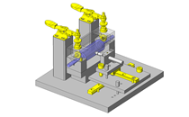
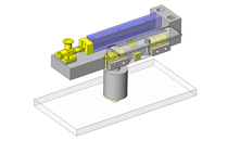
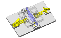
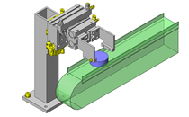
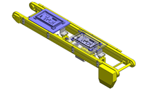
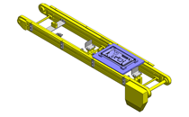
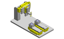
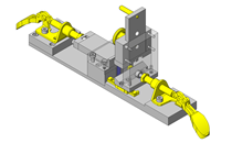
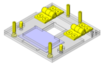
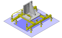
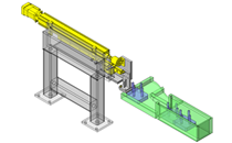
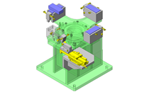
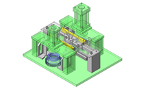
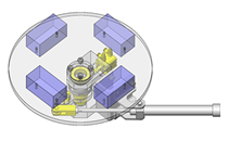
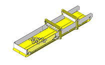
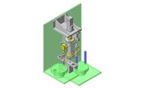
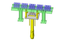
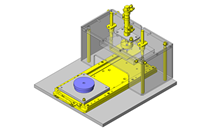
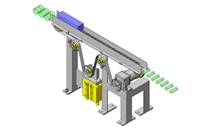
No.000152 XY Floating Mechanism
33
Simplified floating mechanism
Related Category


Miniature Linear Guides
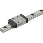
| Product name | Miniature Linear Guides/Standard Blocks/Light Preload |
|---|---|
| Part number | SEB10-55 |
| Features | The most basic type among all the industry standard-compliant blocks. |
Selection criteria
Effective when linear motions are needed in limited space
Available sizes
■Miniature Linear Guides (standard blocks, light preloading, slight clearance)
| Material | Hardness |
|---|---|
| Stainless steel | 56HRC ~ |
| Carbon steel Carbon Steel (Alloy Steel including SCM) | 58HRC ~ |
■Sizes and Dimensions
| Number of Blocks | Block Width | Block Length | Overall Height | Rail Length |
|---|---|---|---|---|
| 1 | 12 | 17.4 | 6 | 25 - 100 |
| 17 | 23.6 | 8 | 40 - 130 | |
| 20 | 30 | 10 | 35 - 275 | |
| 27 | 33.9 | 13 | 45 - 470 | |
| 32 | 42.4 | 16 | 70 - 670 | |
| 40 | 50 | 20 | 100 - 700 | |
| 2 | 12 | 17.4 x 2pcs. | 6 | 70 - 100 |
| 17 | 23.6 x 2pcs. | 8 | 70 - 130 | |
| 20 | 30 x 2pcs. | 10 | 75 - 275 | |
| 27 | 33.9 x 2pcs. | 13 | 95 - 470 | |
| 32 | 42.4 x 2pcs. | 16 | 110 - 670 | |
| 40 | 50 x 2pcs. | 20 | 160 - 700 |
Selection Steps
- Determination on Operating Conditions
- (Moving mass, feed rate, motion pattern, life)
↓
- Temporary selection of linear guide specifications
- (Number of blocks, block type, height and rail length are temporarily selected based on the usage conditions.)
↓
- Basic safety check
-
- ●Allowable Load
- ●Operating Life
- ●Preload
Accuracy Info
■Preload and Accuracy Standards (standard blocks, light preload, slight clearance)

(µm)
| Specification | Light Preload, High Grade | Light Preload, Precision Grade | Slight Clearance, Standard Grade |
|---|---|---|---|
| Radial Clearance | - 3 - 0 | 0 ~ +15 | |
| H Dimension Tolerance | ±20 | ±10 | ±20 |
| Pair variation of H | 15 | 7 | 40 |
| Tolerance of dims. W2 | ±25 | ±15 | ±25 |
| Pair variation of W2 | 20 | 10 | 40 |
■Running Parallelism
(µm)
| Rail length (mm) | ||||||||
|---|---|---|---|---|---|---|---|---|
| - 80 | 81 - 200 | 201 - 250 | 251 - 315 | 316 - 400 | 401 - 500 | 501 - 630 | 631 - 700 | |
| Precision Grade | 2 | 3 | 3.5 | 4 | 5 | 5 | 6 | 6 |
| High Grade | 3 | 7 | 9 | 11 | 11 | 12 | 13.5 | 14 |
| Standard Grade | 13 | 15 | 17 | 18 | 18 | 19 | 21 | 21.5 |
* The slight clearance type has clearances (play) between the rail and blocks.
Performance info.
Rated Load of Linear Guide (wide standard blocks, slight clearance)
| Overall Height | Basic Load Rating | Allowable Static Moment | |||
|---|---|---|---|---|---|
| C (Dynamic) kN | Co (Static) kN | MA N・m | MB N・m | Mc N・m | |
| 6 | 0.3 | 0.6 | 0.8 | 0.8 | 1.5 |
| 8 | 0.9 | 1.5 | 4.1 | 4.1 | 5.2 |
| 10 | 1.5 | 2.5 | 5.1 | 4.1 | 10.2 |
| 13 | 2.2 | 3.3 | 8.8 | 9.5 | 16.1 |
| 16 | 3.6 | 5.4 | 21.6 | 23.4 | 39.6 |
| 20 | 5.2 | 8.5 | 48.4 | 48.4 | 86.4 |
Technical Calculations
■Linear guide life calculations
- ●Life
- When linear guides operate in linear motion while supporting loads, repeated stresses apply on the rolling elements (balls) and raceways (rails), eventually causing scale-like flaking due to material fatigue. The total run distance until this flaking appears is defined as linear guide's "Life".
- ●Rated Life
- Rated life is a total distance 90% of linear guides reach without flaking when a group of the same guides are run under the same condition. The rated life can be calculated with basic dynamic load rating and the load applied on the guides as follows.
-
- When using linear guides, load calculations are initially needed. It is not easy to calculate the loads during linear motion due to vibrations and shocks, as well as load distribution on the guides. Furthermore, operating environment temperature has large effect on life. When these conditions are taken in consideration, the calculations would be as follows.
-

- L: Rated Life (Km)
- fH: Hardness Factor (See Fig.1)
- fT: Temperature Factor (See Fig.2)
- fC: Contact Factor (See Table-1)
- fW: Load Factor (See Table-2)
- C: Basic Dynamic Load Rating (N)
- P: Applied Load (N)
- ●Hardness factor (fH)
-

In using linear guides, the shaft that balls contact must have sufficient hardness, If adequate hardness cannot be obtained, load rating decreases and life will be reduced as a result.
Please correct the rated life with the hardness factor.
- ●Temperature Factor (fT)
-
When the temperature of linear guides exceed 100°C, hardness of blocks and rails will be reduced, causing reduction of life. Please compensate the life rating with temperature factor.
* Please use linear guides within temperature shown on product pages.
- ●Contact Factor (fC)
-
Table-1. Contact Factor
Number of Blocks per Rail Contact Factor fC
1 1.00 2 0.81 3 0.72 4 0.66 5 0.61 In general, it is common to use 2 or more blocks on 1 rail. In such case, load applicable on each block would not be uniform due to machining variations. As the result, allowable load rating on each block would vary depending on the number of blocks used per rail. Please compensate the life rating with contact factor shown on Table-1.
- ●Load Factor (fW)
-
Table-2. Load factor
Application condition fw No external shocks or vibrations and
speed is low 15m/min or less1.0 - 1.5 No significant shocks or vibration and
med. speed 60m/min or less1.5 - 20 External shocks and vibrations exist
and the speed is high 60m/min or over2.0 - 3.5 When calculating loads applicable on linear guides, other than the weight of the object, inertial force due to motion speeds, moment loads, and variations of each over time must also be obtained accurately. However, accurate calculation would be difficult due to repeated starts and stops and various shocks and vibrations. Therefore, the Load Factors shown in Table-2 are used to simplify the life calculations.
- ●Applied Load P Calculation Method
- When moment loads apply a block, use the following formula to convert the moment load to applicable load.
-
- P: Applied Load (N)
- F: Downward load (N)
- Co: Static load rating (N)
- MA: Allowable Static Moment - Pitching Direction (N・m)
- MC: Allowable Static Moment - Rolling Direction (N・m)
- Lp: Load Point Distance (m) in Pitching Direction
- Lr: Load Point Distance (m) in Rolling Direction

Spring Plungers
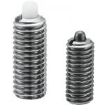
| Product name | Spring Plungers/Stainless Steel |
|---|---|
| Part number | PJXW4-4 |
Selection criteria
Effective as space saving and low price components for positioning reaction force
Available sizes
■Spring Plungers - Stainless Steel
| Nose Material | Load Type | Body | Pin | Spring | Operating Temperature | |
|---|---|---|---|---|---|---|
| Material | Material | Hardness | Material | |||
| Stainless Steel | Ultra Light Load | EN 1.4301 Equiv. | EN 1.4125 Equiv. | 55HRC ~ | EN 1.4568 Equiv. | -30 ~ 260°C |
| Light Load | ||||||
| Heavy Load | ||||||
| Extra Heavy Load | ||||||
| Plastic | Ultra Light Load | Polyacetal | - | -30 ~ 80°C | ||
| Light Load | ||||||
| Heavy Load | ||||||
| Extra Heavy Load | ||||||
■Sizes and Dimensions
| Screw Dia. (Coarse) | Nose | Body length | |
|---|---|---|---|
| Diameter | Stroke | ||
| M3 | Ø1 | 1.5 | 15 |
| 3 | 15 | ||
| M4 | Ø1.6 | 2 | 15 |
| 4 | 24 | ||
| M5 | Ø2 | 3 | 20 |
| 5 | 27 | ||
| M6 | Ø2.5 | 3 | 25 |
| 5 | 30 | ||
| M8 | Ø3.1 | 3 | 25 |
| 5 | 27 | ||
| M10 | Ø3.8 | 5 | 30 |
| 10 | 43 | ||
| M12 | Ø5.5 | 5 | 30 |
| 10 | 43 | ||
| 15 | 51 | ||
| M16 | Ø8 | 10 | 57 |
| 15 | 57 | ||
| 20 | 65 | ||
Performance info.
■Spring Load (N) of Spring Plunger (Stainless Steel)
| Load type | ||||||||||
|---|---|---|---|---|---|---|---|---|---|---|
| Screw Dia. (Coarse) | Nose | Ultra Light Load | Light Load | Heavy Load | Extra Heavy Load | |||||
| Diameter | Stroke | min. | max. | min. | max. | min. | max. | min. | max. | |
| M3 | Ø1 | 1.5 | 0.1 | 0.4 | 0.4 | 1.3 | 0.8 | 2.9 | 1.1 | 3.4 |
| 3 | 0.1 | 0.4 | 0.2 | 1.3 | 0.6 | 2.9 | 0.8 | 3.4 | ||
| M4 | Ø1.6 | 2 | 0.3 | 0.7 | 0.9 | 2.0 | 2.0 | 8.8 | 6.1 | 13.8 |
| 4 | 0.2 | 0.7 | 0.6 | 2.1 | 1.9 | 8.8 | 5.8 | 13.6 | ||
| M5 | Ø2 | 3 | 0.4 | 3.0 | 1.4 | 9.7 | 2.7 | 16.3 | 6.8 | 22.0 |
| 5 | 0.4 | 3.0 | 1.1 | 10.3 | 1.0 | 17.1 | 5.7 | 21.5 | ||
| M6 | Ø2.5 | 3 | 1.8 | 3.1 | 6.0 | 9.8 | 8.0 | 26.4 | 15.8 | 35.6 |
| 5 | 1.5 | 3.1 | 3.4 | 9.86 | 4.4 | 26.6 | 12.9 | 34.4 | ||
| M8 | Ø3.1 | 3 | 1.9 | 3.2 | 6.0 | 9.9 | 14.7 | 27.0 | 21.9 | 36.3 |
| 5 | 1.4 | 3.2 | 4.0 | 9.83 | 6.7 | 26.6 | 14.7 | 34.5 | ||
| M10 | Ø3.8 | 5 | 1.6 | 4.6 | 5.7 | 14.7 | 8.2 | 45.7 | 24.5 | 58.6 |
| 10 | 1.6 | 4.6 | 4.4 | 14.7 | 6.2 | 45.1 | 19.8 | 58.7 | ||
| M12 | Ø5.5 | 5 | 1.7 | 4.7 | 5.8 | 14.7 | 18.2 | 49.0 | 34.9 | 63.6 |
| 10 | 1.6 | 4.7 | 5.0 | 14.7 | 8.2 | 49.1 | 25.5 | 63.6 | ||
| 15 | 1.8 | 4.7 | 6.9 | 14.7 | 7.5 | 48.9 | 20.1 | 63.7 | ||
| M16 | Ø8 | 10 | 2.8 | 10.8 | 9.2 | 34.2 | 18.9 | 68.5 | 38.7 | 88.4 |
| 15 | 2.6 | 10.8 | 8.6 | 34.4 | 14.4 | 68.6 | 33.9 | 88.1 | ||
| 20 | 2.0 | 11.0 | 7.1 | 34.4 | 4.2 | 68.6 | 25.4 | 88.1 | ||
* Min. is the initial load, and max. is the load when the nose is fully compressed.

Adjusting Stopper Screws
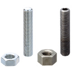
| Product name | Adjusting Stopper Screws/Hexagon Socket/L Configurable/Fine Thread |
|---|---|
| Part number | ANBNS4-25 |
Selection criteria
Effective in that existing product can be used as the pin for determining the reference position.
Available sizes
■Adjusting Pin (Wit hex socket)
| Adjustment Screw | Material | Hardness | Surface Treatment |
|---|---|---|---|
| Fine Thread | EN 1.1191 Equiv. | 45 - 50HRC | Electroless Nickel Plating |
| Trivalent Chromate | |||
| EN 1.7220 Equiv. | 50HRC - | ||
| EN 1.4301 Equiv. | - | - | |
| EN 1.4031 Equiv. | 45HRC - | - | |
| Coarse Thread | EN 1.1191 Equiv. | 45 - 50HRC | Electroless Nickel Plating |
| Trivalent Chromate | |||
| EN 1.7220 Equiv. | 50HRC - | ||
| EN 1.4301 Equiv. | - | - | |
| EN 1.4031 Equiv. | 45HRC - | - |
| Screw Shaft Dia. (mm) | Length (mm) |
|---|---|
| 3 | 10 - 40 (Increments of 5) |
| 4 | 10 - 50 (Increments of 5), 60 |
| 5 | 10 - 50 (Increments of 5), 60 |
| 6 | 15 - 50 (Increments of 5), 60 |

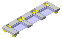
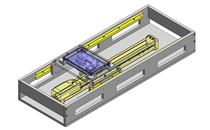
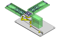
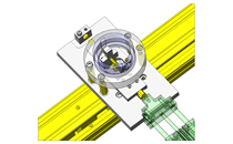
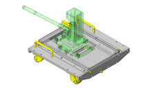
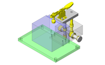
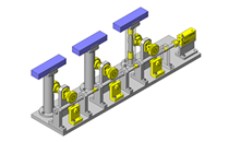
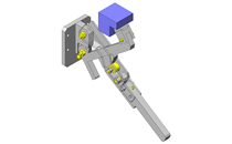
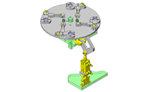
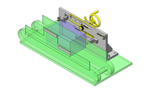
IDEA NOTE Position setting before insertion of workpiece
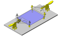
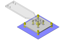
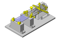
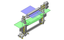
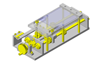
Due to the arrangement of the spring plungers and mounting screws at both ends of each liner guide, adjustment of chuck position to center before insertion of workpiece is facilitated.
-
 Terms of use of CAD data and simplified drawing data
- These terms and conditions (hereinafter referred to as “the Terms") set forth the conditions for downloading CAD data and simplified drawing data provided by MISUMI Corporation (hereinafter referred to as "MISUMI") via www.misumi-europe.com operated by MISUMI Europa GmbH(hereinafter referred to as the "Website"). By downloading CAD data and simplified drawing data posted on the Website (hereafter referred to as “Data”), customers are deemed to have agreed to these Terms.
- 1. Purpose of Use
-
MISUMI offers the following:
1)CAD data found on the Website (3D CAD data, 3D Intermediate data and 2D CAD data) for the purpose of informing customers of the characteristics of the products offered by MISUMI or a manufacturer affiliated with MISUMI for use in their designs.
2)Simplified drawing data (in PDF format) for the purpose of checking the specifications of products. - 2. Characteristics of Data
- There may be a discrepancy in certain characteristics of products (for example: tolerance, surface roughness, chamfer, etc.) between the Data and the actual product. Furthermore, for the purpose of reducing the file size of the Data, some information such as oil groove shapes, threads, or spring shapes, may be removed from the Data.
- 3. Disclaimer
- MISUMI carefully creates the Data but makes no warranty as to the quality, accuracy, functionality, safety, reliability, etc., of the Data. MISUMI may at any time, and with no prior notice to customers, revise or delete Data. MISUMI assumes no responsibility for any damage or loss resulting from any revision or deletion of the Data, or any errors in said data. Customers are solely responsible for all aspects of their own designs, including those made using the Data. MISUMI may provide customers with design example data on the Website, but the quality, accuracy, functionality, safety, reliability, etc., of such data are not guaranteed. MISUMI may, at any time, and in its sole discretion, request that the customer cease its use of or destroy the Data in its possession. MISUMI may request the customer provide MISUMI documentation of such destruction.
- 4.Prohibited Acts
-
Customers or users of the Data, are prohibited from the following acts regarding the Data, in whole or in part:
(1)Requesting quotations or placing orders for products with third parties other than those authorized by MISUMI or its affiliates;
(2)Receiving quotations or orders for products from third parties by providing the Data to a third party or using the Data in their own business;
(3)Displaying links to the Website related to the Data on their own websites, etc., without consent of MISUMI or its affiliates;
(4)Using or reproducing the Data beyond the scope of the above-stated Purpose of Use;
(5)Modifying, altering, tampering with, translating, or adapting the Data;
(6)Selling, transferring, lending, sublicensing, or providing the Data to third parties in any way without consent of MISUMI or its affiliates;
(7)Altering the content, reverse engineering, decompiling, disassembling, or analyzing the Data;
(8)Publicly disclosing or exhibiting the Data without consent of MISUMI or its affiliates;
(9)Using the Data for the purpose of providing products and services identical or similar to those of MISUMI or its affiliates;
(10)Performing acts that interfere with the proper functioning of this Website, such as acquiring Data in bulk. - 5. Copyright
-
All title and copyright in and to any information contained in the Data are owned by MISUMI or the relevant manufacturer affiliated with MISUMI and are protected by applicable copyright laws and international treaties. By downloading Data, the customer acquires no ownership rights of any kind in the intellectual property contained within. Without prior approval from MISUMI, no part of the Data may be utilized (reproduced, modified, reverse-engineered, uploaded, presented, sent, distributed, licensed, sold, or published) for any purpose other than that mentioned above.
In the event Data is found to have been to be used for any purpose other than that mentioned above or against any applicable laws or the Terms, MISUMI may pursue any legal remedy available to it, which may result in forbidding the offending user from using the Data or accessing the Website. - 6. Third-Party Data
- MISUMI offers some Data provided by third parties. Such Data may be subject to separate terms and conditions, in addition to these terms. MISUMI makes no guarantee or warranty regarding Data from third parties.
- 7. Export Control
- Customers shall comply with all applicable laws and regulations regarding the export of the Data.
- 8. Amendments to the Terms
- MISUMI may, at any time, and in its sole discretion, modify these terms and conditions; any such modification will be effective immediately.
- 9. Severability
- If any term or provision of these Terms is invalid, illegal, or unenforceable in any jurisdiction, such invalidity, illegality, or unenforceability shall not affect any other term or provision of these Terms or invalidate or render unenforceable such term or provision in any other jurisdiction. Section 139 BGB (German Civil Code) shall not apply.
- 10.Miscellaneous
-
In the event that Customers violate the Terms, MISUMI and/or MISUMI Europa GmbH shall be entitled to claim the damages and expenses (including attorney's fees) incurred by such violation against the Customers.
These Terms and any disputes arising in connection therewith shall be exclusively governed by and construed in accordance with the laws of the Federal Republic of Germany, without regard to its conflicts of law principles. The courts located in Frankfurt am Main/Germany shall have exclusive jurisdiction to adjudicate any dispute arising in connection with these Terms. By downloading the Data, you agree to submit to the exclusive and personal jurisdiction of the courts located in Frankfurt am Main/Germany. - Revised: September 21, 2025
CAD Data Download (Unit Assembly)
CAD Data Download: File Format
Cautions on the CAD data
-
Assembly data shows the assembly drawings in the concept design phase. The sole purpose of the data is to explain the structure and functionality of the assembly and is not considered nor to be used as a final design.
You will need to edit the Data so that it meets your specific design conditions. -
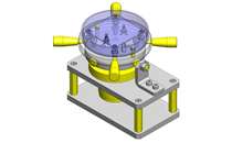
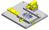
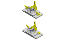
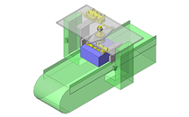
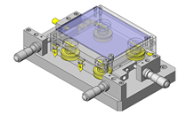
The CAD data unit assembly consists of sub-assemblies.
Each sub-assembly unit can be used as it is or can be edited. - The Data for fabricated parts is based on easy-to-edit dimensions and shapes in sketches and histories.
- The Data including the third-part components are made by the Company.
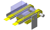
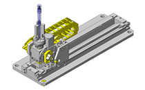
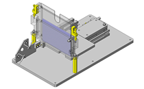
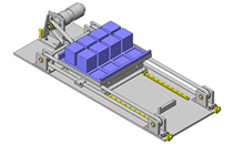
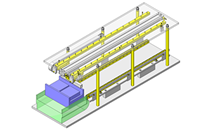
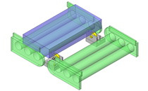
* The part in the frame is a sub-assembly unit.
-

- * Unit assembly CAD data consists of some sub-assemblies.
Each sub-assembly unit can be used as it is or can be edited.
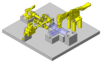
Application Overview
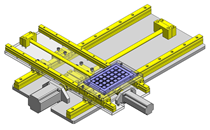
Purpose
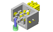
- Purpose
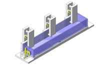
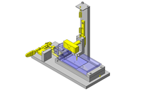
- To fit bushing onto roughly-positioned pin.
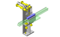
- Operation
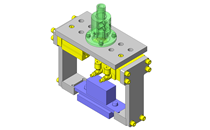
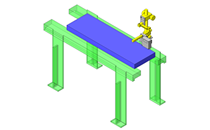
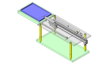
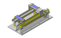
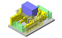
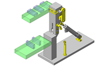
- This mechanism is designed to perform floating in the X and Y directions via two linear guides installed between the lift unit and the bushing chuck. Before inserting the bushing into the pin, the bushing chuck is at the center position. The lift unit lowers the bushing and bushing chuck. The bushing is floated toward the pin and then fit on the pin. After fitting the bushing, the bushing chuck is returned to the center by the spring plunger.
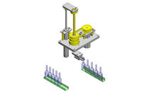
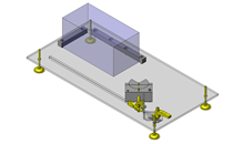
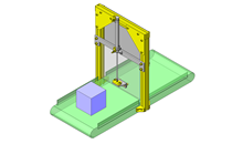
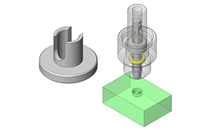
Target workpiece
- (1) Bushing
- Shape: cylinder
- Size: Ø20 x H20mm
- Weight: 7g
- (2) Pin
- Shape: column
- Size: Ø7 x H15mm
- Weight: 110g
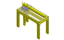
Design Specifications
Operating Conditions or Design Requirements
- Vertical stroke by lift unit: 38mm
- Allowable maximum displacement between inserting workpiece and inserted workpiece: L = 1.5mm
- Outer dimensions: W88 x D100 x H96mm
Required Performance
- Positioning accuracy: ±0.1mm
Selection Criteria for Main Components
- Spring Plungers
- To enable the bushing chuck to be returned to the center position when the inserting workpiece is unclamped, select spring plungers whose minimum load is larger than the seal resistance of the linear guide, which is between 2N and 5N.
Design Evaluation
Verification of main components
- Comparative verification of centering force and spring plunger clamp power is conducted to see whether centering of workpiece is possible.
- Check of the centering force of inserting workpiece and the spring plunger clamp power
- Conditional value: centering pin taper angle of inserted workpiece θ = 23°, downward clamp force of lift unit P = 30N, gravitational acceleration g = 9.8m/s², friction coefficient: µ = 0.2 (metal and metal)
- Friction angle: ψ, from µ = tanψ, ψ = tan - 1µ = tan - 1 (0.2) = 11.3°
- The inserting workpiece centering force F is, from P = F x tan (θ + ψ), F = P / (tan (θ + ψ)) = 30 / (tan (23 + 11.3)) = 44.0N
- Spring plunger clamp power PS = 5.8 to 13.6N = inserting workpiece centering force F = 44.0N
⇒ As the inserting workpiece centering force is sufficiently larger than the spring plunger clamp power, centering cannot be prevented. The chuck position can be returned to the center before workpiece insertion.
Other Design Consideration
- As the pressing face of the plunger is subjected to the load of lateral movement, smoothly finish it.
Explore Similar Application Examples


Payment Method


On-Demand Manufacturing
Certificates


Copyright © MISUMI Corporation All Rights Reserved.