
- inCAD Library Home
- > No.000149 Lifting and Carrying Mechanism Using Eccentric Shaft
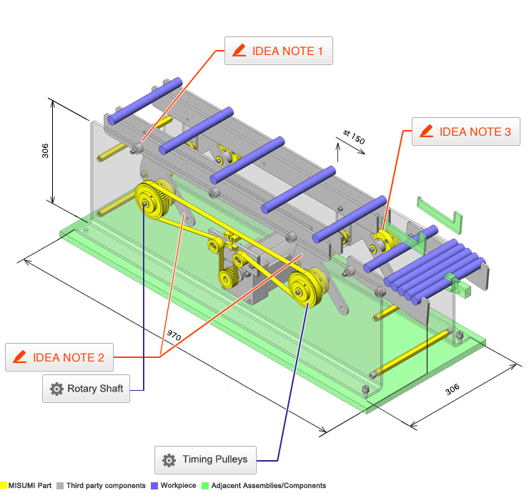
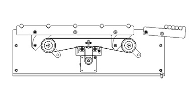
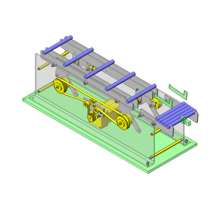
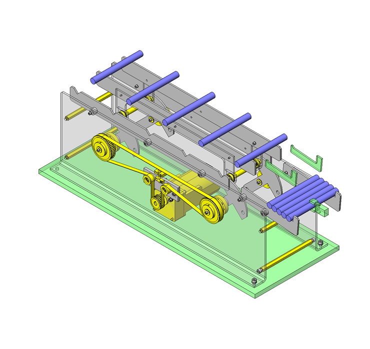
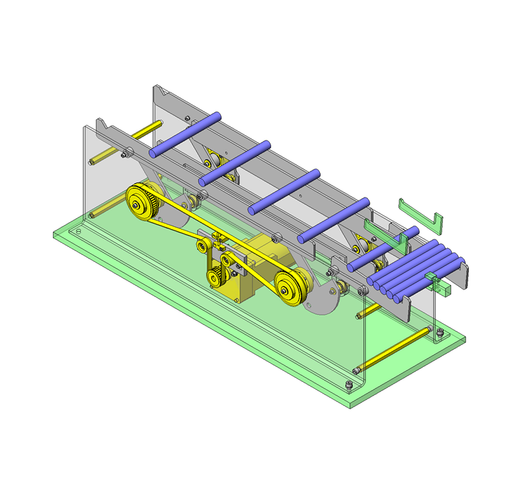
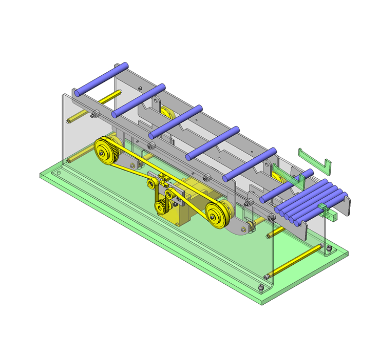
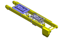
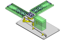
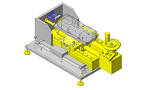
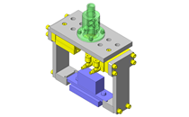
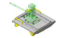
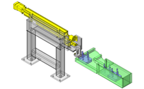
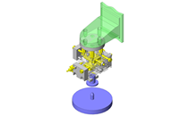
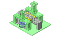
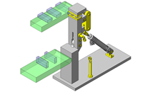
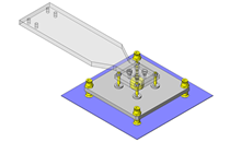
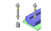
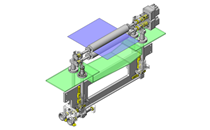
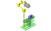
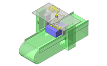
No.000149 Lifting and Carrying Mechanism Using Eccentric Shaft
94
Lift and carry by a single actuator
Related Category


Rotary Shaft
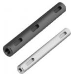
| Product name | Rotary Shafts/Both Ends Tapped with Key Grooves |
|---|---|
| Part number | PSFHKRW15-76-M5-N5-KA0-A25-KB56-B20 |
| Features | Tolerance Options: g6 (ground), h7 (ground) and h9 polished |
Selection criteria
Effective because engineered components requiring accuracy such as keyway are available in the market.
Available sizes
■Rotary Shaft (Both Ends Tapped, with Keyway Type)
| O.D. tolerance | Material | Surface Treatment |
|---|---|---|
| h9 (Cold-drawn) | EN 1.1191 Equiv. | Black Oxide |
| Electroless Nickel Plating | ||
| EN 1.4301 Equiv. | - | |
| h7 (Ground) | EN 1.1191 Equiv. | Black Oxide |
| Electroless Nickel Plating | ||
| EN 1.4301 Equiv. | - | |
| g6 (Ground) | EN 1.1191 Equiv. | Black Oxide |
| Electroless Nickel Plating | ||
| EN 1.4301 Equiv. | - |
■Sizes
| O.D. Tolerance | O.D. |
Length
(Configure in 1mm increments) |
|---|---|---|
| h9 | O6 | 20.0 ~ 300.0 |
| O8 | 20.0 ~ 400.0 | |
| O10 | 20.0 ~ 500.0 | |
| O12 | 30.0 ~ 600.0 | |
| O15 | 30.0 ~ 700.0 | |
| O20 | 40.0 ~ 800.0 | |
| O25 | 50.0 ~ 800.0 | |
| O30 | 60.0 ~ 800.0 | |
| O35 | 70.0 ~ 800.0 | |
| h7 | O6 | 20.0 ~ 300.0 |
| O8 | 20.0 ~ 400.0 | |
| O10 | 20.0 ~ 500.0 | |
| O12 | 30.0 ~ 600.0 | |
| O15 | 30.0 ~ 700.0 | |
| O20 | 40.0 ~ 800.0 | |
| O25 | 50.0 ~ 800.0 | |
| O30 | 60.0 ~ 800.0 | |
| O35 | 70.0 ~ 800.0 | |
| O40 | 80.0 ~ 800.0 | |
| O50 | 100.0 ~ 800.0 | |
| g6 | O6 | 20.0 ~ 300.0 |
| O8 | 20.0 ~ 400.0 | |
| O10 | 20.0 ~ 500.0 | |
| O12 | 30.0 ~ 600.0 | |
| O13 | 30.0 ~ 600.0 | |
| O15 | 30.0 ~ 700.0 | |
| O16 | 30.0 ~ 800.0 | |
| O17 | 40.0 ~ 800.0 | |
| O18 | 40.0 ~ 800.0 | |
| O20 | 40.0 ~ 800.0 | |
| O22 | 40.0 ~ 800.0 | |
| O25 | 50.0 ~ 800.0 | |
| O30 | 60.0 ~ 800.0 | |
| O35 | 70.0 ~ 800.0 | |
| O40 | 80.0 ~ 800.0 | |
| O50 | 100.0 ~ 800.0 |
■Detailed Keyway Dimensions of Rotary Shaft
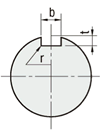
| Shaft Dia. | b | t | r | ||
|---|---|---|---|---|---|
| Reference Dim. | Tolerance | Reference Dim. | Tolerance | ||
| 6 | 2 |
- 0.004
- 0.029 |
1.2 |
+0.1
0 |
0.08 ~
0.16 |
| 8 ・ 10 | 3 | 1.8 | |||
| 12 | 4 |
0
- 0.03 |
2.5 | ||
| 13 ~ 17 | 5 | 3.0 |
0.16 ~
0.25 |
||
| 18 ~ 22 | 6 | 3.5 | |||
| 25 ・ 30 | 8 |
0
- 0.036 |
4.0 |
+0.2
0 |
|
| 35 | 10 | 5.0 |
0.25 ~
0.4 |
||
| 40 | 12 |
0
- 0.043 |
5.0 | ||
| 50 | 14 | 5.5 | |||
Accuracy Info
■O.D. Tolerance Table
| O.D. | O.D. Tolerance | ||
|---|---|---|---|
| h9 | h7 | g6 | |
| O6 |
0
- 0.030 |
0
- 0.012 |
- 0.004
- 0.012 |
| O8 |
0
- 0.036 |
0
- 0.015 |
- 0.005
- 0.014 |
| O10 | |||
| O12 |
0
- 0.043 |
0
- 0.018 |
- 0.006
- 0.017 |
| O13 | - | - | |
| O15 |
0
- 0.043 |
0
- 0.018 |
|
| O16 | - | - | |
| O17 | - | - | |
| O18 | - | - | |
| O20 |
0
- 0.052 |
0
- 0.021 |
- 0.007
- 0.020 |
| O22 | - | - | |
| O25 |
0
- 0.052 |
0
- 0.021 |
|
| O30 | |||
| O35 |
0
- 0.062 |
0
- 0.025 |
- 0.009
- 0.025 |
| O40 | - | ||
| O50 | - | ||

Timing Pulleys
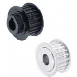
| Product name | High Torque Timing Pulleys/5GT |
|---|---|
| Part number | GPA50GT5120-A-N15 |
| Features | Circular Tooth Profile Pulleys with minimal backlash, suitable for positioning. |
Selection criteria
Effective to transmit the driving force without causing slipping or speed changes
Available sizes
■Timing Pulleys (5GT Type)
| Material | Surface Treatment |
Accessory
Set Screw |
|
|---|---|---|---|
| Pulley | Flange | ||
|
EN AW-2017 Equiv.
(Duralumin) |
EN AW-5052 Equiv. | Clear Anodize | EN 1.4301 Equiv. |
| EN 1.1191 Equiv. | Low Carbon Steel | - |
Chromium-molybdenum steel
(Black Oxide) |
| Black Oxide | |||
■Sizes and Dimensions
| Number of teeth |
Nominal
Width |
Pulley
Shape |
Shaft Bore
Specs. |
Shaft Bore Specs.(Configure in 1mm increments) | |||||||||||||
|---|---|---|---|---|---|---|---|---|---|---|---|---|---|---|---|---|---|
| Straight Bore | Straight Bore + Tap | New JIS Keywayed Bore + Tap |
Stepped Holes - Stepped Holes
(Counterbore Holes on the Hub Side) |
Both Ends Stepped Bore | |||||||||||||
| Hole Dia. | Hole Dia. | Counterbore Hole Dia. |
Counterbore
Depth |
Hole Dia. | Counterbore Hole Dia. |
Counterbore
Depth |
|||||||||||
| No Hub | With Hub | No Hub | With Hub | No Hub | With Hub | No Hub | With Hub | No Hub | With Hub | With Hub, without Hub | No Hub | No Hub | No Hub | ||||
| 14 |
9
12 15 |
No Hub
With Hub |
Straight Bore
Straight Bore +Tap New JIS Keywayed Bore + Tap Stepped Hole Stepped Hole (Counterbore Holes on the Hub Side) Both Ends Stepped Bore |
6 - 10 | 6 - 8 | 6 - 8 | - | - | - | 6 | - | 8 | - |
(When no hub)
2.0 ? Counterbore depth ? Ridge width - 2.0 (When with hub) 2.0 ? Counterbore depth ? Full length - 2.0 |
6 | 8 |
3-14
Total of counterbore depth ? Width - 3 |
| 15 | 6 - 10 | 6 - 10 | 6 - 8 | 6 - 8 | 6 | 8 - 10 | 8 | 6 - 8 | 8 - 10 | ||||||||
| 16 | 6 - 12 | 6 - 12 | 6 - 10 | 6 | 8 | 6 - 10 | 6 - 8 | 8 - 12 | 8 - 10 | 6 - 10 | 8 - 12 | ||||||
| 18 | 6 - 14 | 6 - 14 | 6 - 13 | 6 - 9 | 8 - 10 | 6 - 10 | 6 - 10 | 8 - 12 | 8 - 12 | 6 - 12 | 8 - 14 | ||||||
| 20 | 6 - 16 | 8 - 15 | 8 - 14 | 8 - 10 | 8 - 12 | 8 | 8 - 14 | 8 - 13 | 10 - 16 | 10 - 15 | 8 - 14 | 10 - 16 | |||||
| 22 | 8 - 19 | 8 - 19 | 8 - 17 | 8 - 12 | 8 - 12 | 8 | 8 - 17 | 8 - 14 | 10 - 19 | 10 - 16 | 8 - 17 | 10 - 19 | |||||
| 24 | 8 - 22 | 8 - 22 | 8 - 18 | 8 - 16 | 8 - 14 | 8 - 10 | 8 - 20 | 8 - 16 | 10 - 23 | 10 - 18 | 8 - 20 | 10 - 22 | |||||
| 25 | 8 - 22 | 8 - 22 | 8 - 20 | 8 - 16 | 8 - 16 | 8 - 12 | 8 - 20 | 8 - 18 | 10 - 23 | 10 - 20 | 8 - 20 | 10 - 22 | |||||
| 26 | 10 - 27 | 10 - 24 | 10 - 21 | 10 - 16 | 10 - 17 | 10 - 13 | 10 - 25 | 10 - 20 | 12 - 27 | 12 - 22 | 10 - 25 | 12 - 27 | |||||
| 28 | 10 - 27 | 10 - 27 | 10 - 24 | 10 - 20 | 10 - 19 | 10 - 15 | 10 - 25 | 10 - 25 | 12 - 27 | 12 - 27 | 10 - 25 | 12 - 27 | |||||
| 30 | 10 - 28 | 10 - 28 | 10 - 26 | 10 - 22 | 10 - 20 | 10 - 16 | 10 - 26 | 10 - 26 | 12 - 28 | 12 - 28 | 10 - 26 | 12 - 28 | |||||
| 32 | 10 - 32 | 10 - 30 | 10 - 30 | 10 - 22 | 10 - 23 | 10 - 17 | 10 - 30 | 10 - 26 | 12 - 32 | 12 - 28 | 10 - 30 | 12 - 32 | |||||
| 34 | 12 - 37 | 12 - 32 | 12 - 32 | 12 - 24 | 12 - 26 | 12 - 18 | 12 - 35 | 12 - 28 | 14 - 37 | 14 - 30 | 12 - 35 | 14 - 37 | |||||
| 36 | 12 - 37 | 12 - 34 | 12 - 34 | 12 - 26 | 12 - 30 | 12 - 20 | 12 - 35 | 12 - 30 | 14 - 37 | 14 - 32 | 12 - 35 | 14 - 37 | |||||
| 40 | 12 - 42 | 12 - 36 | 12 - 36 | 12 - 26 | 12 - 30 | 12 - 22 | 12 - 40 | 12 - 32 | 14 - 42 | 14 - 34 | 12 - 40 | 14 - 42 | |||||
| 44 | 12 - 50 | 12 - 38 | 12 - 42 | 12 - 26 | 12 - 30 | 12 - 23 | 12 - 48 | 12 - 34 | 14 - 50 | 14 - 36 | 12 - 48 | 14 - 50 | |||||
| 48 | 12 - 55 | 12 - 42 | 12 - 45 | 12 - 30 | 12 - 30 | 12 - 26 | 12 - 53 | 12 - 38 | 14 - 55 | 14 - 38 | 12 - 53 | 14 - 55 | |||||
| 50 | 12-59 | 12 - 42 | 12 - 45 | 12 - 30 | 12 - 30 | 12 - 27 | 12 - 57 | 12 - 38 | 14 - 59 | 14 - 40 | 12 - 57 | 14 - 59 | |||||
| 60 | 12 - 72 | 12 - 44 | 12 - 45 | 12 - 30 | 12 - 30 | 12 - 30 | 12 - 70 | 12 - 40 | 14 - 72 | 14 - 42 | 12 - 70 | 14 - 72 | |||||
Selection steps
■Timing pulley selection steps
* Select the timing belt together with the timing pulley.
The automated selection tool is available
Link opens to Japanese Calculation link
- Determine Operating Conditions
- Designed power, rotational speed, rotation ratio, interim shaft distance, motion pattern, etc.
↓
- Belt temporary selection
- Belt type/Belt width
↓
- Verification of specifications applicability
-
- Confirmation of calculated shaft distance, etc.
- Confirmation of belt tension and load
Accuracy Info
■Shaft Bore Dia. of Timing Pulley
| Shaft Bore Dia. |
Tolerance
(H7) |
|---|---|
| 6 - 10 |
+0.015
0 |
| 10 - 18 |
+0.018
0 |
| 18 - 30 |
+0.021
0 |
| 30 - 50 |
+0.025
0 |
| 50 - 80 |
+0.030
0 |
Motors with Electromagnetic Brake
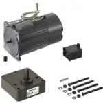
| Product name | Small gearhead motor with electromagnetic brake |
|---|---|
| Part number | PACMB90-W40-V100 |
Selection criteria
Effective for the equipment requiring strong brake force or heavy load
Available sizes
■Motors with Electromagnetic Brake
| Type | Outer Dimensions | Output (W) | Voltage (V) | Shaft Length | Gear Head Length | Motor Length |
|---|---|---|---|---|---|---|
|
Single-phase
3-Phase |
60 | 6 | 100 | 32 | 26 | 75 |
| 200 | ||||||
| 70 | 15 | 100 | 30 | 80 | ||
| 200 | ||||||
| 80 | 25 | 100 | 30 | 85 | ||
| 200 | ||||||
| 90 | 40 | 100 | 37 | 105 | ||
| 200 | ||||||
| 60 | 100 | 38 | 50 | 120 | ||
| 200 | ||||||
| 90 | 100 | 130 | ||||
| 200 |
The 3-phase motor can be used in 220 V.
Selection steps
■Small geared motor selection steps
- Determination of the Driving Facility
- Specify the driving facility and overall dimensions, then check required conditions for the driving facility, such as the mass and travel speed of the material to be transferred.
↓
- Calculation of rotational speed and load
- Calculate the load torque, loading moment of inertia and rotational speed at the motor driving shaft.
↓
- Confirmation of Required Specifications
- Confirm the required specifications, position accuracies, position holding, speed ranges, operating environment, and environmental resistance, etc. at the drive section and equipment.
↓
- Motor Model Selection
- Select the models most suitable for the required specifications.
↓
- Interim Selection of Motor and Gearhead
- Select motor and gearhead candidates based on calculated rotational speeds, load torque and inertia values as well as the selected motor models.
↓
- Confirmation of the Selected Motor
- Finalize the selection by confirming that all the specifications of the motor and the gearhead adequately meet the requirements.
Performance info.
■Small Size Geared Motor (Speed, Load)
| Type | Outer Dimensions | Output (W) | Voltage (V) | 50Hz | 60Hz | ||||
|---|---|---|---|---|---|---|---|---|---|
| Rated |
Starting Torque
(N・m) |
Rated |
Starting Torque
(N・m) |
||||||
|
Rotational Speed
(r/min) |
Torque
(N・m) |
Rotational Speed
(r/min) |
Torque
(N・m) |
||||||
| Single-phase | 60 | 6 | 100 | 1300 | 0.044 | 0.056 | 1600 | 0.035 | 0.056 |
| 200 | 1300 | 0.044 | 0.056 | 1600 | 0.035 | 0.056 | |||
| 70 | 15 | 100 | 1300 | 0.11 | 0.10 | 1600 | 0.088 | 0.10 | |
| 200 | 1300 | 0.11 | 0.10 | 1600 | 0.088 | 0.10 | |||
| 80 | 25 | 100 | 1300 | 0.19 | 0.20 | 1600 | 0.16 | 0.20 | |
| 200 | 1300 | 0.19 | 0.20 | 1600 | 0.16 | 0.20 | |||
| 90 | 40 | 100 | 1300 | 0.29 | 0.32 | 1625 | 0.24 | 0.32 | |
| 200 | 1300 | 0.29 | 0.32 | 1625 | 0.24 | 0.32 | |||
| 60 | 100 | 1275 | 0.45 | 0.57 | 1600 | 0.36 | 0.57 | ||
| 200 | 1275 | 0.45 | 0.57 | 1600 | 0.36 | 0.57 | |||
| 90 | 100 | 1225 | 0.7 | 0.68 | 1525 | 0.56 | 0.70 | ||
| 200 | 1225 | 0.7 | 0.68 | 1525 | 0.56 | 0.70 | |||
| Type | Outer Dimensions | Output (W) | Voltage (V) | 50Hz | 60Hz | ||||
|---|---|---|---|---|---|---|---|---|---|
| Rated |
Starting Torque
(N・m) |
Rated |
Starting Torque
(N・m) |
||||||
|
Rotational Speed
(r/min) |
Torque
(N・m) |
Rotational Speed
(r/min) |
Torque
(N・m) |
||||||
| 3-Phase | 80 | 25 | 200 | 1350 | 0.18 | 0.54 | 1625 | 0.15 | 0.4 |
| 1375 | 0.18 | 0.66 | 1650 | 0.15 | 0.5 | ||||
| 90 | 40 | 1350 | 0.28 | 0.72 | 1625 | 0.24 | 0.51 | ||
| 1375 | 0.27 | 0.88 | 1675 | 0.23 | 0.63 | ||||
| 60 | 1350 | 0.42 | 1.0 | 1625 | 0.35 | 0.69 | |||
| 1375 | 0.41 | 1.2 | 1650 | 0.34 | 0.87 | ||||
| 90 | 1350 | 0.63 | 1.6 | 1625 | 0.53 | 1.1 | |||
| 1400 | 0.62 | 2.0 | 1650 | 0.52 | 1.4 | ||||
Technical Calculations
■Technical Calculations for Electromagnetic Brake Motors

IDEA NOTE Accurate pitch feed is made possible by reasonably-priced AC motor
As the positioning grooves receive workpieces at the start and end of the feed, the accurate pitch feed is possible with reasonably-priced AC motor.


-

-
 Terms of use of CAD data and simplified drawing data
- These terms and conditions (hereinafter referred to as “the Terms") set forth the conditions for downloading CAD data and simplified drawing data provided by MISUMI Corporation (hereinafter referred to as "MISUMI") via www.misumi-europe.com operated by MISUMI Europa GmbH(hereinafter referred to as the "Website"). By downloading CAD data and simplified drawing data posted on the Website (hereafter referred to as “Data”), customers are deemed to have agreed to these Terms.
- 1. Purpose of Use
-
MISUMI offers the following:
1)CAD data found on the Website (3D CAD data, 3D Intermediate data and 2D CAD data) for the purpose of informing customers of the characteristics of the products offered by MISUMI or a manufacturer affiliated with MISUMI for use in their designs.
2)Simplified drawing data (in PDF format) for the purpose of checking the specifications of products. - 2. Characteristics of Data
- There may be a discrepancy in certain characteristics of products (for example: tolerance, surface roughness, chamfer, etc.) between the Data and the actual product. Furthermore, for the purpose of reducing the file size of the Data, some information such as oil groove shapes, threads, or spring shapes, may be removed from the Data.
- 3. Disclaimer
- MISUMI carefully creates the Data but makes no warranty as to the quality, accuracy, functionality, safety, reliability, etc., of the Data. MISUMI may at any time, and with no prior notice to customers, revise or delete Data. MISUMI assumes no responsibility for any damage or loss resulting from any revision or deletion of the Data, or any errors in said data. Customers are solely responsible for all aspects of their own designs, including those made using the Data. MISUMI may provide customers with design example data on the Website, but the quality, accuracy, functionality, safety, reliability, etc., of such data are not guaranteed. MISUMI may, at any time, and in its sole discretion, request that the customer cease its use of or destroy the Data in its possession. MISUMI may request the customer provide MISUMI documentation of such destruction.
- 4.Prohibited Acts
-
Customers or users of the Data, are prohibited from the following acts regarding the Data, in whole or in part:
(1)Requesting quotations or placing orders for products with third parties other than those authorized by MISUMI or its affiliates;
(2)Receiving quotations or orders for products from third parties by providing the Data to a third party or using the Data in their own business;
(3)Displaying links to the Website related to the Data on their own websites, etc., without consent of MISUMI or its affiliates;
(4)Using or reproducing the Data beyond the scope of the above-stated Purpose of Use;
(5)Modifying, altering, tampering with, translating, or adapting the Data;
(6)Selling, transferring, lending, sublicensing, or providing the Data to third parties in any way without consent of MISUMI or its affiliates;
(7)Altering the content, reverse engineering, decompiling, disassembling, or analyzing the Data;
(8)Publicly disclosing or exhibiting the Data without consent of MISUMI or its affiliates;
(9)Using the Data for the purpose of providing products and services identical or similar to those of MISUMI or its affiliates;
(10)Performing acts that interfere with the proper functioning of this Website, such as acquiring Data in bulk. - 5. Copyright
-
All title and copyright in and to any information contained in the Data are owned by MISUMI or the relevant manufacturer affiliated with MISUMI and are protected by applicable copyright laws and international treaties. By downloading Data, the customer acquires no ownership rights of any kind in the intellectual property contained within. Without prior approval from MISUMI, no part of the Data may be utilized (reproduced, modified, reverse-engineered, uploaded, presented, sent, distributed, licensed, sold, or published) for any purpose other than that mentioned above.
In the event Data is found to have been to be used for any purpose other than that mentioned above or against any applicable laws or the Terms, MISUMI may pursue any legal remedy available to it, which may result in forbidding the offending user from using the Data or accessing the Website. - 6. Third-Party Data
- MISUMI offers some Data provided by third parties. Such Data may be subject to separate terms and conditions, in addition to these terms. MISUMI makes no guarantee or warranty regarding Data from third parties.
- 7. Export Control
- Customers shall comply with all applicable laws and regulations regarding the export of the Data.
- 8. Amendments to the Terms
- MISUMI may, at any time, and in its sole discretion, modify these terms and conditions; any such modification will be effective immediately.
- 9. Severability
- If any term or provision of these Terms is invalid, illegal, or unenforceable in any jurisdiction, such invalidity, illegality, or unenforceability shall not affect any other term or provision of these Terms or invalidate or render unenforceable such term or provision in any other jurisdiction. Section 139 BGB (German Civil Code) shall not apply.
- 10.Miscellaneous
-
In the event that Customers violate the Terms, MISUMI and/or MISUMI Europa GmbH shall be entitled to claim the damages and expenses (including attorney's fees) incurred by such violation against the Customers.
These Terms and any disputes arising in connection therewith shall be exclusively governed by and construed in accordance with the laws of the Federal Republic of Germany, without regard to its conflicts of law principles. The courts located in Frankfurt am Main/Germany shall have exclusive jurisdiction to adjudicate any dispute arising in connection with these Terms. By downloading the Data, you agree to submit to the exclusive and personal jurisdiction of the courts located in Frankfurt am Main/Germany. - Revised: September 21, 2025
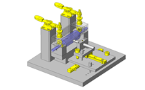
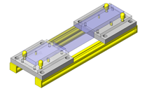
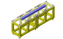
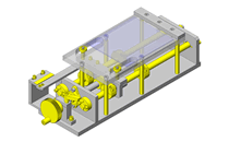
CAD Data Download (Unit Assembly)
CAD Data Download: File Format
Cautions on the CAD data
-
Assembly data shows the assembly drawings in the concept design phase. The sole purpose of the data is to explain the structure and functionality of the assembly and is not considered nor to be used as a final design.
You will need to edit the Data so that it meets your specific design conditions. -
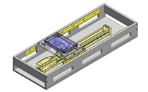
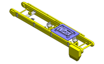
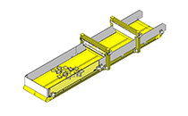
The CAD data unit assembly consists of sub-assemblies.
Each sub-assembly unit can be used as it is or can be edited. - The Data for fabricated parts is based on easy-to-edit dimensions and shapes in sketches and histories.
- The Data including the third-part components are made by the Company.
* The part in the frame is a sub-assembly unit.
-

- * Unit assembly CAD data consists of some sub-assemblies.
Each sub-assembly unit can be used as it is or can be edited.
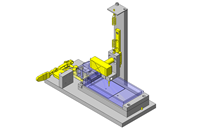
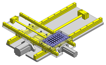
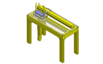
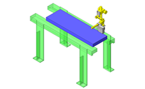
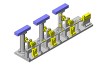
Application Overview
Purpose
- Purpose
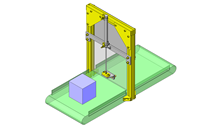
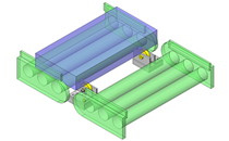
- To perform accurate pitch feed of cylinder-shaped workpiece.
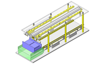
- Operation
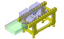
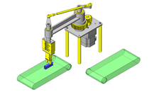
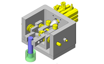
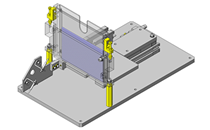
- As appearance inspection and NG product ejection are performed at the final position, workpieces move from one positioning groove to the next positioning groove one by one.
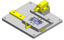
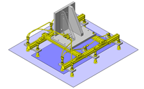
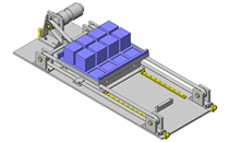
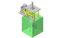
Target workpiece
- Shape: aluminum cylinder part
- Size: O20 x 200mm
- Weight: 0.15kg
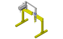
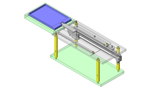
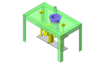
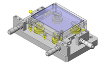
Design Specifications
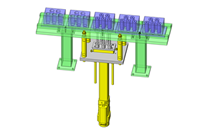
Operating Conditions or Design Requirements
- Movement amount and movement pitch: 150mm
- Movement speed: 1sec. / pitch
- Outer dimensions: W970 x D306 x H306mm
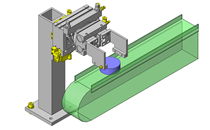
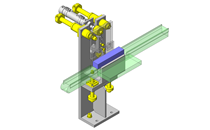
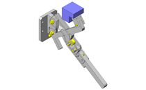
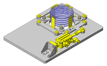
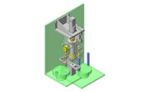
Selection Criteria for Main Components
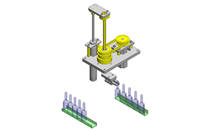
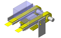
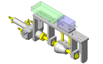
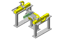
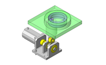
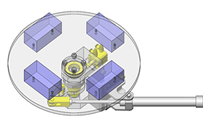
- To allow a movement amount of 150mm, the misalignment amount from the rotation center to the rotation edge is set to 75mm.
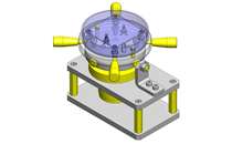
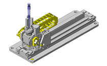
- Timing belt is used to drive two eccentric shafts.
- Selected a gear ratio that enables the speed of 1 pitch/second.
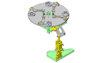
Design Evaluation
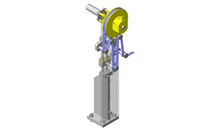
Verification of main components
- Select motor based on load torque and moment of inertia.
- Here, calculation for selection of AC motor is explained.
- Select gear ratio based on workpiece movement time.
- Conditional value: movement time per stroke = approx. 1.0sec., motor rotation speed = 1,300rpm, timing pulley ratio = 50 : 25 = 2 : 1
- 60 x gear ratio x 2 / 1.0 ? motor rotation speed Therefore, from gear ratio ? (1,300 x 1.0) / (2 x 60) = 10.8, select 1 : 10 for the gear ratio (i) of gearhead.
- Calculation of load torque
- Conditional value: g = 9.807 (m/s2), m = 2 (kg), η = 0.81, r = 0.075m
- From T'm = F・r/η and F = m・g,
T'm = 2 x 9.807 x 0.075/0.81 = 1.816N・m
Considering safety factor Sf = 2 and pulley ratio, the load torque Tm is:
Tm = T'm x Sf / 2 = 1.816 x 2 / 2 = 1.816N・m - Check of loading moment of inertia
Moment of inertia applied to large belt pulley: J1 = 1.8162 x 10⁻²kg・m2
Moment of inertia of small belt pulley: J2 = 1.3312 x 10-?kg・m2
From moment of inertia applied to small belt pulley: Jd = J2 + J1 (b / a)2 (b / a = pulley ratio), Jd = 1.3312 x 10-? + 1.8162 x 10-2 x (25/50)2?= 4.554 x 10⁻³kg・m2
Moment of inertia in motor shaft is, from Jm = Jd・(1 / i)2,
Jm = 4.554 x 10-3 x (1 / 10)2 = 4.554 x 10-? (kg・m2) = 0.455kg・cm2 - From allowable moment of inertia of PACMB90-40W-100V = 0.735 (kg・cm2) and allowable torque of ACMGX90-10 = 2.25 (N・m), 0.735 (kg・cm2) > 0.455 (kg・cm2), 2.25 (N・m) > 1.816 (N・m)?
-> Specifications are satisfied.
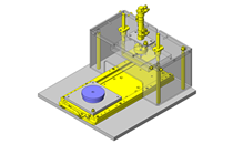
Other Design Consideration
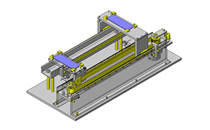
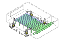
- The movement amount accuracy depends on the machining accuracy of the workpiece receiving part. Therefore, the required accuracy is the workpiece receiving part manufacturing accuracy.
- The cover of the timing belt is omitted from this drawing for illustrative reasons, but in the actual machine, the cover is mounted for safety and dust prevention purposes.
- The maximum movement value in the specifications represents the movement amount due to misalignment amount, but by changing the workpiece receiving position, the movement amount can be changed accordingly.
Explore Similar Application Examples


Payment Method


On-Demand Manufacturing
Certificates


Copyright © MISUMI Corporation All Rights Reserved.