- Angle of Oscillation A
- 180°
- 180°
- Torque(N▪m)
- Torque(N▪m)
- 5.3
- Valve
- Allowable Kinetic Energy(J)
- Allowable Kinetic Energy(J)
- 0.4
- Size
- 40
- Switch
- Lead wire(m)
- 3
- Number of switches
- Port types
- Shaft pattern
- Made to order specifications
- Starting point of rotation
- Connector type
- Specifications
- Cushioning
- Type
- CAD
- 2D
- 3D
- Becsült szállítási napok
- Minden
- 26 munkanapok belül
Compact Rotary Actuator, Rack and Pinion Type, CRQ2 Series (CDRQ2BS40-180C-M9NL)

Termékadatok
Model Number Notation
Model Number Notation
Compact Rotary Actuator, Rack & Pinion Type, CRQ2 Series Specifications
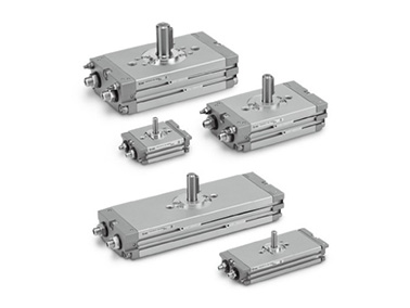
CRQ2 Series external appearance
| Size | 10 | 15 | 20 | 30 | 40 |
|---|---|---|---|---|---|
| Fluid | Air (non-lube) | ||||
| Max. operating pressure | 0.7MPa | 1.0MPa | |||
| Min. operating pressure | 0.15MPa | 0.1MPa | |||
| Ambient and fluid temperature | 0 to 60℃ (No freezing) | ||||
| Cushion | Rubber bumper | Not attached, Air cushion | |||
| Angle adjustment range | Rotation end ±5° | ||||
| Rotation | 90°, 180°, 360° | ||||
| Port size | M5×0.8 | Rc1/8, G1/8, NPT1/8, NPTF1/8 | |||
| Output (Nm)* | 0.3 | 0.75 | 1.8 | 3.1 | 5.3 |
Rotation Range
When pressurized from the port indicated by the arrow, the shaft will rotate in a clockwise direction.
Rotating angle: 90°
Rotating angle: 180°
Rotating angle: 360°
External dimensional drawing
(Unit: mm)
Size 10, 15 dimensional drawing
(Unit: mm)
| Size | Rotating angle | A | AU* | B | BA | BB | BC | BD | BU | D (g6) | DD (h9) | H |
|---|---|---|---|---|---|---|---|---|---|---|---|---|
| 10 | 90°, 180°, 360 ° | 42.4 | (8.5) | 29 | 8.5 | 17 | 6.7 | 2.2 | 16.7 | 5 | 12 | 18 |
| 15 | 90°, 180°, 360 ° | 53.6 | (9.5) | 31 | 9 | 26.4 | 10.6 | - | 23.1 | 6 | 14 | 20 |
*The AU dimension is not the dimension at the time of shipment, since its dimension is for adjustment parts.
(Unit: mm)
| Size | Rotating angle | W | Q | S | US | UW | ab | M | TA | TC | TD |
|---|---|---|---|---|---|---|---|---|---|---|---|
| 10 | 90 ° | 4.5 | 17 | 56 | 35 | 44 | 6 | 9 | 15.5 | 8 | 15.4 |
| 180 ° | 69 | ||||||||||
| 360 ° | 97 | ||||||||||
| 15 | 90 ° | 5.5 | 20 | 65 | 40 | 50 | 7 | 10 | 16 | 9 | 17.6 |
| 180 ° | 82 | ||||||||||
| 360 ° | 116 |
S: upper 90°, middle 180°, lower 360 °
Size 20, 30, 40 dimensional drawing
*Double shaft: øD is the shaft dimension.
(Unit: mm)
| Size | Rotating angle | A | AU* | B | BA | BB | BC | BD | BE | BU |
|---|---|---|---|---|---|---|---|---|---|---|
| 20 | 90°, 180°, 360 ° | 63 | (11) | 50 | 14 | 34 | 14.5 | - | - | 30.4 |
| 30 | 90°, 180°, 360 ° | 69 | (11) | 68 | 14 | 39 | 16.5 | 49 | 16 | 34.7 |
| 40 | 90°, 180°, 360 ° | 78 | (13) | 76 | 16 | 47 | 18.5 | 55 | 16 | 40.4 |
| Size | CA | CB | D (g6) | DD (h9) | F | H | J | JA | JB |
|---|---|---|---|---|---|---|---|---|---|
| 20 | 7 | 5 | 10 | 25 | 2.5 | 30 | M8 × 1.25 | 11 | 6.5 |
| 30 | 8.1 | 5.3 | 12 | 30 | 3 | 32 | M10 × 1.5 | 14 | 8.5 |
| 40 | 8.3 | 5.5 | 15 | 32 | 3 | 36 | M10 × 1.5 | 14 | 8.6 |
*The AU dimension is not the dimension at the time of shipment, since its dimension is for adjustment parts.
(Unit: mm)
| Size | Rotating angle | JJ | K | Q | S | W | Dimensions: key | US | |
|---|---|---|---|---|---|---|---|---|---|
| b | L1 | ||||||||
| 20 | 90 ° | - | 3 | 29 | 104 | 11.5 | 4 (-0.03 to 0) | 20 | 59 |
| 180 ° | 130 | ||||||||
| 360 ° | 180 | ||||||||
| 30 | 90 ° | M5 × 0.8 depth 18 | 4 | 33 | 122 | 13.5 | 4 (-0.03 to 0) | 20 | 65 |
| 180 ° | 153 | ||||||||
| 360 ° | 216 | ||||||||
| 40 | 90 ° | M6 × 1 depth 7 | 5 | 37 | 139 | 17 | 5 (-0.03 to 0) | 25 | 73 |
| 180 ° | 177 | ||||||||
| 360 ° | 253 | ||||||||
| Size | TA | TB | TC | TD | TF (H9) | TG (H9) | TL | UW | G | M | N | L |
|---|---|---|---|---|---|---|---|---|---|---|---|---|
| 20 | 24.5 | 1 | 13.5 | 27 | 4 | 4 | 2.5 | 74 | 8 (-0.1 to 0) | 15 | 11 | 9.6 (-0.1 to 0) |
| 30 | 27 | 2 | 19 | 36 | 4 | 4 | 2.5 | 83 | 10 (-0.1 to 0) | 18 | 13 | 11.4 (-0.1 to 0) |
| 40 | 32.5 | 2 | 20 | 39.5 | 5 | 5 | 3.5 | 93 | 11 (-0.1 to 0) | 20 | 15 | 14 (-0.1 to 0) |
*In addition to Rc1/8, G1/8, NPT1/8 and NPTF1/8 are also available.
S: upper 90°, middle 180°, lower 360 °
Drawing
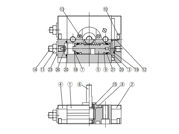
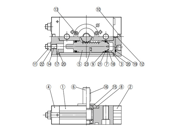
Standard type / size 10, 15 structure drawing
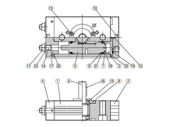
Standard type / size 20, 30, 40 structure drawing
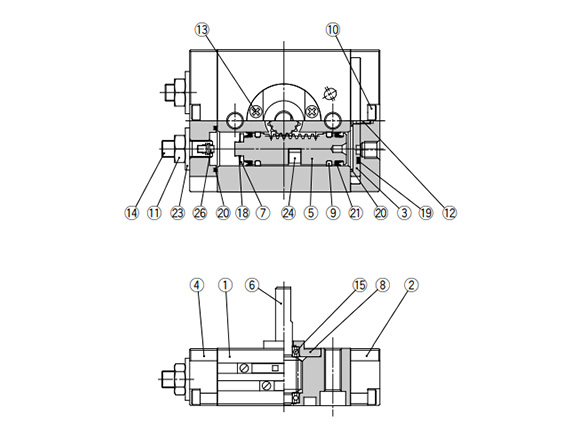
With auto switch / size 10, 15 structure drawing
With auto switch / size 20, 30, 40 structure drawing
- (1) Main body: aluminum alloy (anodized)
- (2) Cover: aluminum alloy (chromated, painted)
- (3) Plate: aluminum alloy (chromated)
- (4) End cover: aluminum alloy (chromated, painted)
- (5) Piston: stainless steel
- (6) Shaft: stainless steel (size: 10, 15) / chrome molybdenum steel (size: 20, 30, 40)
- (7) Seal retainer: aluminum alloy (chromated)
- (8) Bearing retainer: aluminum alloy (chromated)
- (9) Wear ring: resin
- (10) Hex socket head cap screw: stainless steel
- (11) Hex nut (size: 10, 15) / small hex nut (size: 20, 30, 40): steel wire
- (12) Cross-head No. 0 screw: steel wire
- (13) Cross-head No. 0 screw (size: 10, 15) / cross recessed screw (size: 20, 30, 40): steel wire
- (14) Hex socket head set screw: chrome molybdenum steel
- (15) Bearing: bearing steel
- (16) Parallel key: carbon steel (size: 20, 30, 40 only)
- (17) Steel ball: stainless steel (size: 20, 30, 40 only)
- (18) Type CS retaining ring: stainless steel
- (19) Seal: NBR
- (20) Gasket: NBR
- (21) Piston seal: NBR
- (22) Cushion seal: rubber material (size: 20, 30, 40 with cushion only)
- (23) Seal washer: NBR
- (24) Magnet: - (with auto switch only)
- (25) Cushion valve assembly (size: 20, 30, 40 with cushion only)
- (26) Cushion pad: rubber material (size: 10, 15)
Precautions
- *Be sure to read the precautions in the catalog before use.
- *The angle adjusting screw (angle adjustment bolt) is set at random near the maximum rotating angle. Therefore, it must be readjusted to obtain the angle that suits your application.
- *See the manufacturer's catalog for product information other than the above.
Részletes információk
Alapvető információk
[Features]
· Uses internal cushioning.
· The main body can also serve as a flange.
· With angle adjustment mechanism (each rotation end ±5°).
· 360° rotating angle type.
· Piping can be installed from one end.
· 2 auto switches can be mounted on the same side (mountable on both sides).
· A double piston design free from backlash.
· Shaft type: Supports both single and double shafts.
· Centering is easy when mounting the body.
Vigyázat
- Refer to the catalog for details on product specifications.
- Product images may be representative. Refer to the manufacturer's catalog for details.