Szűrési feltételek
- Nut type
- Flange Type
- Compact Flanged
- Shaft O.D. D(φ)
- 6
- 8
- 10.4
- Shaft material
- Nut Overall Length(mm)
- 25
- 40
- Nut O.D.(φ)
- 14
- 16
- 21
- Shaft Overall Length L(mm)[60–600/1mm egység]
- Nut Material
- Grease
- M(mm)
- 3
- 4
- 5
- Type
- CAD
- 2D
- 3D
- Becsült szállítási napok
- Minden
- 10 munkanapok belül
- 12 munkanapok belül
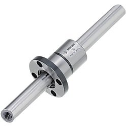
Ball Splines / Both Ends Tapped
Cikkszám:
javaslat található.Vázlatrajz és specifikációs táblázat
Dimensional Drawing
 | Flange type nut orientation ● 1-Nut Type | ● 2-Nut Type |
 |  | |
| [ ! ] When selecting Overall Length (L Dimension), check the annealing range. | ||
| [ ! ] For the included nut, please select a shape from below. | ||
| ■Round Flanged |
 |
| ■Compact Flanged |
 |
| ■Straight Nuts | |
 | [A]Dimension of Included Key |
[ ! ] The key is press fit into the nut.
| One End Tapped | Spline Shaft [M] EN 1.3505 Equiv., Nut [M] EN 1.7242 Equiv. [H]Hardness: 58HRC or more | Spline Shaft and Nut [M] Material: EN 1.4125 Equiv. [H]Hardness: 55 HRC or more |
| Nut 1 pc. | Nut 1 pc. | |
| With Round Flange Nut | BSFM | BSFMS |
| With Compact Flange Nut | BSFN | — |
| With Straight Nut | BSFS | BSFSS |
[ ! ] Spline Shafts are hardened, and need to be annealed before machining.
[ ! ] As the accuracy is guaranteed as a set of nut and shaft, they are not sold separately.[ ! ] A dust-proof seal is attached to the nut, so the balls will not fall off even if the spline shaft is pulled out.
(If the spline shaft is inserted at an angle to the nut, the ball may fall out.)
Specification Table
| Part Number | — | L | — | M |
BSFS10 BSFS10G BSFS10G BSFS10L BSFS10L | — — — | 350 350 350 | — — — | M5 M5 M5 |
■Spline Shafts
[ ! ] For BSFMS and BSFSS, only * marked sizes are available, and the Max. L dimension is in ( ).
[ ! ] For BSFN, only No. 6, 8 and 10 are available.
[ ! ] Operating Temp.: Plastic components are used in ball spline assemblies. Avoid using in high temperature environments: keep below 80°C.
| Part Number | L: 1 mm Increments | M (Coarse) Selection | D | Mass (kg/m) | ||||||||
| Type | No. | 1-Nut Type | ||||||||||
| BSFM BSFN BSFS BSFMS BSFSS | * 6 | 60 to 500 (190) | 3 | 6 | 0.23 | |||||||
| * 8 | 60 to 600 (190) | 3 | 4 | 8 | 0.39 | |||||||
| * 10 | 60 to 800 (390) | 3 | 4 | 5 | 10.4 | 0.65 | ||||||
| * 13 | 60 to 800 (390) | 4 | 5 | 6 | 13.4 | 1.11 | ||||||
| * 16 | 70 to 1000 (390) | 4 | 5 | 6 | 8 | 16.6 | 1.65 | |||||
| 20 | 80 to 1000 | 5 | 6 | 8 | 10 | 20.6 | 2.57 | |||||
| 25 | 90 to 1300 | 5 | 6 | 8 | 10 | 12 | 25.8 | 4.04 | ||||
| 30 | 100 to 1300 | 6 | 8 | 10 | 12 | 16 | 30.8 | 5.85 | ||||
[ ! ] For BSFN, only No. 6, 8 and 10 are available.
[ ! ] Operating Temp.: Plastic components are used in ball spline assemblies. Avoid using in high temperature environments: keep below 80°C.
[ ! ] Lubrication: Ball splines are lubricated at the time of shipment, but should be re-lubricated after installation in equipment.
After you start using the vehicle, fill the grease every 100 km.
For re-lubrication, Lithium soap-based grease (Alvania Grease S2 by Showa Shell Sekiyu) is recommended.
■Round Flange Nuts, Compact Flange Nuts
[!] Dimensions in () are for EN 1.4125 Equiv. [!] Allowable static moment M01 are values measured when a single nut is used, and M02 are values measured when two nuts are used in contact.
| No. | D (h6) | L | df | H | P.C.D. | d1 | d2 | h | W | d | B | Basic Rated Torque | Basic Load Rating | Allowable Static Moment | Mass (kg) | |||
| Dynamic Ct (N⋅m) | Static C0 t (N⋅m) | Dynamic C (kN) | Static C0 (kN) | M01 (N⋅m) | M02 (N⋅m) | |||||||||||||
| 6 | 14 | 25 | 30 | 6 | 22 | 3.5 | 6 | 3.1 | 6.5 | 1.5 | 18 | 3.8 | 7 | 1.2 | 2.1 | 5 | 36 | 0.03 |
| 8 | 16 | 32 | 24 | 21 | 4.8 | 8.7 | 1.2 | 2.1 | 5 | 36 | 0.04 | |||||||
| 10 | 21 | 40 (33) | 42 (41) | 6 (8) | 32 (30) | 4.5 | 8 | 4.4 (5.3) | 14 (8.5) | 25 | 19 (11) | 34 (21) | 3.8 (2.4) | 6.9 (4.3) | 26 (15) | 181 (102) | 0.09 | |
| 13 | 24 | 44 (36) | 44 (45) | 7 (8) | 33 (34) | 15 (10) | — | 28 (20) | 52 (37) | 4.6 (3.3) | 8.3 (5.9) | 36 (22) | 251 (148) | 0.11 | ||||
| 16 | 31 | 50 | 51 | 7 | 40 | 4.4 | 18 | 51 | 93 | 6.2 | 11.1 | 56 | 386 | 0.2 | ||||
| 20 | 35 | 63 | 58 | 9 | 45 | 5.5 | 9.5 | 5.4 | 22.5 | 2 | 85 | 154 | 8.5 | 15.3 | 83 | 611 | 0.3 | |
| 25 | 42 | 71 | 65 | 52 | 26.5 | 193 | 348 | 15.4 | 27.7 | 173 | 1248 | 0.4 | ||||||
| 30 | 47 | 80 | 75 | 10 | 60 | 6.6 | 11 | 6.5 | 30 | 2.5 | 272 | 490 | 18.5 | 33.3 | 212 | 1581 | 0.57 | |
■Straight Nuts
[!] Dimensions in () are for EN 1.4125 Equiv. [!] Allowable static moment M01 are values measured when a single nut is used, and M02 are values measured when two nuts are used in contact.
| No. | D (h6) | L | b | t (+0.05 0) | d | α | Basic Rated Torque | Basic Load Rating | Allowable Static Moment | Mass (kg) | Dimensions of Key (Included) | |||||||||
| Tolerance | Dynamic Ct (N⋅m) | Static C0 t (N⋅m) | Dynamic C (kN) | Static C0 (kN) | M01 (N⋅m) | M02 (N⋅m) | B | h | L1 | R | ||||||||||
| Tolerance | Tolerance | |||||||||||||||||||
| 6 | 14 | 25 | 2.5 | +0.014 0 | 1.2 | 1.5 | 15° | 3.8 | 7 | 1.2 | 2.1 | 5 | 36 | 0.012 | 2.5 | +0.016 +0.006 | 2.5 | 0 −0.025 | 10.5 | 1.25 |
| 8 | 16 | 25° | 4.8 | 8.7 | 1.2 | 2.1 | 5 | 36 | 0.013 | 10.5 | ||||||||||
| 10 | 21 | 40 (33) | 3 | 1.5 | — | 19 (11) | 34 (21) | 3.8 (2.4) | 6.9 (4.3) | 26 (15) | 181 (102) | 0.06 | 3 | 3 | 17 (14) | 1.5 | ||||
| 13 | 24 | 44 (36) | 28 (20) | 52 (37) | 4.6 (3.3) | 8.3 (5.9) | 36 (22) | 251 (148) | 0.07 | 17 (14) | ||||||||||
| 16 | 31 | 50 | 3.5 | +0.018 0 | 2 | 51 | 93 | 6.2 | 11.1 | 56 | 386 | 0.15 | 3.5 | +0.024 +0.012 | 3.5 | 0 −0.030 | 18 | 1.75 | ||
| 20 | 35 | 63 | 4 | 2.5 | 2 | 85 | 154 | 8.5 | 15.3 | 83 | 611 | 0.2 | 4 | 4 | 29 | 2 | ||||
| 25 | 42 | 71 | 193 | 348 | 15.4 | 27.7 | 173 | 1248 | 0.29 | 33 | ||||||||||
| 30 | 47 | 80 | 2.5 | 272 | 490 | 18.5 | 33.3 | 212 | 1581 | 0.37 | 42 | |||||||||
Alterations
| Part Number | — | L | — | M | — | (SC·FC·NTW) |
| BSFS10 | — | 350 | — | M5 | — | SC15 |
| Alterations | Wrench Flats | Set Screw Flat | Additional Spline Nuts | |||||||||||||||||||||||||||||||||||||||
 |  |  | ||||||||||||||||||||||||||||||||||||||||
| Code | SC | FC | NTW | |||||||||||||||||||||||||||||||||||||||
| Spec. |
|
| Adds a nut. (from one to two) [ ! ] BSFS·BSFM Applicable to BSFN only | |||||||||||||||||||||||||||||||||||||||
[ ! ] The angles / positions of alterations such as wrench flats, set screw flat, and keyway are not on the same plane.
[ ! ] It is not possible to specify the key of the spline nut or the positional relationship between the mounting hole and alteration.
Cikkszámlista
Elemek száma
| Cikkszám |
|---|
Egységár (HÉA nélkül)(egységár adóval) | Normál feladási dátum |
|---|
- ( - ) | 10 munkanapok |
- ( - ) | 12 munkanapok |
- ( - ) | 12 munkanapok |
- ( - ) | 10 munkanapok |
- ( - ) | 12 munkanapok |
- ( - ) | 12 munkanapok |
- ( - ) | 10 munkanapok |
- ( - ) | 12 munkanapok |
- ( - ) | 12 munkanapok |
Részletes információk
Alapvető információk
Vigyázat
- Please check the content on our website as the PDF does not contain the most up-to-date information.
Vázlat és specifikációk
Specifications/Overview
| Precautions for Ball Spline Assembly |  |
| ■Check Assembly Position | |
| Match Mark Numbers are entered on nuts and spline shafts (see the diagram on the right). | |
| When re-assembling, confirm the match mark numbers, character orientations, and positional relationship of parts. | |
| If the alignment marks are not aligned correctly, the function will be affected. | |
| ■Tolerance for Mating Bores | |
| H7 tolerance is recommended for mating bores for the spline nuts when mounting them on housings. | |
| ■For Customers machining the shaft ends | |
| In order to facilitate nut insertions, chamfer the machined shaft ends, and remove burrs on the edges of the spline groove with a round file. |